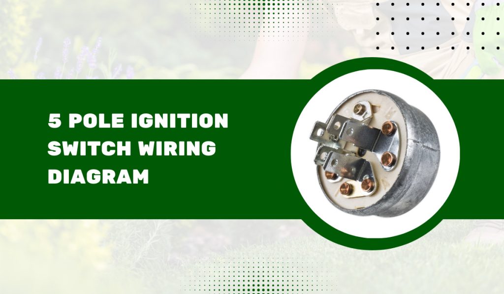
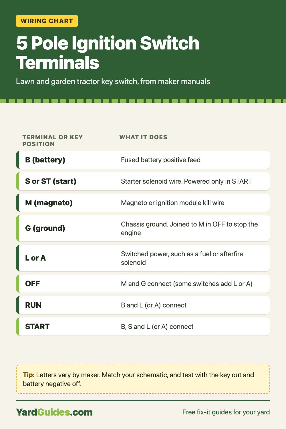
Quick answer: On most 5 pole lawn and garden tractor key switches the terminals are B (fused battery positive), S (starter solenoid), M (magneto or ignition module kill wire), G (ground) and L or A (switched power, often a fuel or afterfire solenoid). In OFF, M connects to G so the engine stops. In RUN, B connects to L (or A). In START, B connects to S and L. Makers vary the letters and add contacts, so check your model’s wiring schematic, then test the switch with a meter, key out and battery negative off.
Jump to the table: 5 pole ignition switch wiring diagram: what each terminal does ↓
Safety first: Do all of this with the engine off, the key out of the switch, the parking brake set, the PTO off, the deck or implements lowered to the ground and the wheels blocked. Disconnect the battery negative cable before you unplug anything. Kubota’s manual puts the rule simply: “always disconnect the ground cable (-) of battery first and reconnect it last” (Kubota BX operator’s manual, Safe Operation p. 9). Never jumper the key switch terminals or bypass a seat, PTO, brake or neutral switch to get a machine running.
5 pole ignition switch wiring diagram: what each terminal does
A key switch is printed with letters, not wire colors. John Deere’s technical manual puts it this way: “Key switch terminals are identified to coincide with electrical schematic designations” (John Deere STX38 TM, Key Switch Tests p. 4-70, via ManualsDir). So the letter on the switch matches the letter on your tractor’s schematic, and that’s what you wire to.
Here is what the maker documents we found say each terminal does on a 5 terminal mower or lawn tractor switch:
| Terminal | What it connects to | Source |
|---|---|---|
| B (battery) | Fused battery positive feed. Cub Cadet: “the fused red wire with white trace connects to the B terminal.” | Cub Cadet RZT-S shop manual p. 62 |
| S or ST (start) | Starter solenoid trigger wire. “Battery power from the B terminal is directed to the start circuit through the S terminal.” | Cub Cadet p. 62; JD STX38 p. 4-70 |
| M (magneto) | The magneto or ignition module kill wire. “M is connected to the magneto by a yellow wire.” | Cub Cadet p. 61 |
| G (ground) | Chassis ground. “G is connected to ground by a green wire.” | Cub Cadet p. 61 |
| L or A | Switched power in RUN and START. On the Cub Cadet RZT-S, “L is connected to the after fire solenoid.” John Deere’s STX38 switch uses A in the same spot. | Cub Cadet p. 61; JD STX38 p. 4-70 |
Wire colors are not a standard. The yellow and green above are Cub Cadet’s colors on one model. Go by the letters and your own schematic.
Which terminals connect in OFF, RUN and START
This is the part a wiring diagram is really for. Here’s the continuity each maker lists:
| Key position | John Deere STX38 (A, B, G, M, ST) | Cub Cadet RZT-S (B, S, M, G, L) | Briggs & Stratton harness switch 5020927 (6 terminals) |
|---|---|---|---|
| OFF | G and M | M, G and L | G, M and A |
| RUN | A and B | B and L | B, L and A |
| START | A, B and ST | B, S and L | B, L and S |
Sources: JD STX38 TM p. 4-70 (via ManualsDir), Cub Cadet RZT-S shop manual pp. 61 to 62 (via ManualsDir), Briggs & Stratton 5108762 harness diagram (dealer-hosted copy).
The pattern is the same across all three:
- OFF grounds the magneto. M connects to G. Cub Cadet explains: “In the OFF position, the magneto primary windings are grounded, disabling the ignition system.” Some switches also ground the fuel solenoid or accessory contact (L or A) in OFF.
- RUN powers the run circuit. B connects to L (or A), which feeds things like the fuel or afterfire solenoid.
- START adds the starter. B connects to S, and L (or A) stays powered so the engine can fire while it cranks.
Variants you’ll run into
- L versus A. Same job, different letter. Wire it to whatever your schematic shows on that letter.
- Six or seven terminals. The Briggs & Stratton harness above uses a 6 terminal switch (M, L, G, B, S, A). Many replacement switches add terminals too. A 6 terminal switch can replace a 5 terminal one only if its continuity chart covers the same contacts. Check the chart printed on the package or the maker’s sheet before you buy.
- Switches marked I, R or ACC. Those letters belong to a different style of switch (often automotive or industrial). Don’t assume I means M or R means L. Use that switch maker’s own diagram.
Why a mis-wired switch can leave an engine that won’t shut off
On a magneto engine, turning the key to OFF doesn’t cut power to the spark. It grounds the magneto through M and G. If the M wire is off, broken or on the wrong terminal, or the G terminal has no ground, the engine keeps running with the key off. Cub Cadet’s shop manual lists this exact symptom, “engine runs with key in OFF position,” and the check is continuity between the M and G terminals with the key in OFF (Cub Cadet RZT-S shop manual p. 61).
Free printable: seasonal maintenance checklist for your mower & tractor
A 2-page spring-to-winter checklist for riding and push mowers and compact tractors. Then short, practical emails a couple of times a month. Unsubscribe anytime.
If that happens, stop the engine the way your operator’s manual describes for that model, then fix the wiring before you use the machine again. Don’t put it back in service until the key stops it every time.
Ignition switch wiring diagnostic table
| Symptom | Likely cause | Check (manual section) | Fix |
|---|---|---|---|
| Engine keeps running with key OFF | M wire off or broken, G not grounded, or switch not closing M to G | Cub Cadet RZT-S shop manual, Electrical, key switch p. 61: continuity M to G in OFF, G wire to ground | Repair the M or G wire; replace the switch if M to G is open in OFF |
| Key to START, nothing happens | No power at B (fuse or feed), switch not closing B to S, or an interlock open | Cub Cadet RZT-S p. 62: power at B, then B to S in START | Fix the fused feed; replace a switch that fails B to S; check the seat, brake and PTO switches per your manual |
| Cranks but won’t start, or dies when the key returns to RUN | B to L (or A) not closing, so the fuel or afterfire solenoid gets no power | Cub Cadet RZT-S p. 62: B and L in RUN and START | Replace the switch if B to L is open; otherwise trace the L wire |
| Dies when you stand up or release the brake | Interlock doing its job, or a faulty seat or brake switch | Cub Cadet RZT-S p. 70, Engine shut-down circuits | Use the controls as the manual says; test and replace a bad interlock switch. Never bypass it |
| Meter shows continuity across connector pins with the switch unplugged | Shorting connector built into the harness | Briggs & Stratton 5108762 harness diagram note (dealer-hosted copy) | Test the switch terminals themselves, not the harness plug |
| Replacement switch has different letters | Different switch style (A vs L, 6 terminals, or I/R/ACC type) | JD STX38 TM p. 4-70 (via ManualsDir): letters match the schematic | Match each letter to your schematic; return a switch whose continuity chart doesn’t match |
How to test a 5 pole ignition switch with a multimeter
John Deere’s procedure is to disconnect the key switch connector and “use an ohmmeter to test switch continuity in OFF, RUN, and START positions,” then: “If any continuity is NOT correct, replace switch” (JD STX38 TM p. 4-70). Here’s that test written out for any 5 terminal switch.
What you’ll need – A digital multimeter with a continuity or ohms setting – The wiring schematic or key switch continuity chart for your model (operator’s manual, technical manual or the switch package) – Masking tape and a marker to label wires
Steps 1. Park and secure the machine. Level ground, parking brake set, PTO off, deck lowered, wheels blocked. 2. Key out, battery negative off. Pocket the key while you remove the switch. Disconnect the negative battery cable. 3. Unplug the switch. If the switch has separate spade wires instead of a plug, label each wire with its terminal letter before you pull it. 4. Remove the switch from the dash so you can see the letters on the back. 5. Zero the meter. Set it to continuity or the lowest ohms range and touch the probes together. 6. Put the key in the switch on the bench and set it to OFF. Check M to G. You should have continuity. Check that B shows no continuity to S or to L (or A). 7. Turn to RUN. B to L (or A) should show continuity. M to G should now be open. B to S should be open. 8. Hold in START. B to S and B to L (or A) should both show continuity. 9. Compare with your model’s chart. Anything missing, or a reading that flickers as you wiggle the key, means a worn switch. Replace it.
If the switch passes, the problem is in the wiring, the fuse, the solenoid or an interlock. Our Cub Cadet voltage regulator problems and Simplicity mower electrical problems guides cover the next places to look. If you’ve lost the key on a Kubota, see how to start a Kubota tractor without a key for the safe options.
How to wire a replacement 5 pole ignition switch
- Get the right switch. Order by your machine’s model and serial number, or match the replacement’s continuity chart to the original. Same letters is not enough on its own.
- Battery negative off, key out.
- Move one wire at a time. Take a wire off the old switch and put it on the same letter on the new one. On a plug-in switch, the harness plug does this for you.
- Don’t add or skip contacts. If the new switch has an extra terminal your harness doesn’t use, leave it empty unless your schematic says otherwise. Don’t add a jumper between terminals.
- Keep the fuse in the B feed. Cub Cadet’s B wire is described as fused. Don’t remove a fuse or fusible link to make a wire reach.
- Reconnect the battery negative last.
- Check it works the way the maker intends. Seated, brake set, PTO off: it should crank in START and run in RUN. Turn the key to OFF and the engine must stop. Then check your interlocks the way your operator’s manual describes before you mow.
Safety switches are part of this circuit: leave them connected
The key switch doesn’t work alone. Seat, brake, PTO and neutral switches are wired into the same start and kill circuits. On the Cub Cadet RZT-S, “The seat switch and brake switch work in series to ground the magneto primary windings” so the engine stops when you leave the seat without the brake set (Cub Cadet RZT-S shop manual p. 70). Those switches have to stay in the circuit, connected and working.
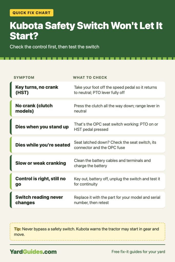
Farm safety specialists put it plainly: “Do not disable or wire around the safety interlocks installed by the manufacturer” (Farm and Ranch eXtension in Safety and Health, Preventing Tractor Runover Incidents). If a safety switch is the reason your machine won’t start, test and replace it. Our guides to the Kubota safety switch, the zero turn safety switch and Toro zero turn safety switch problems walk through that.
Adding a dash gauge while the panel is open? See how to wire an amp gauge on a tractor.
Charge the battery first: see how to charge a riding mower battery.
FAQ
What are the 5 terminals on a lawn mower ignition switch? Usually B (battery), S (starter solenoid), M (magneto), G (ground) and L or A (switched power for a fuel or afterfire solenoid or accessories). John Deere’s STX38 switch is marked A, B, G, M and ST. Always match the letters to your own schematic.
Which terminals connect when the key is off? M and G, which grounds the magneto and stops the engine. Some switches also connect L or A in OFF: Cub Cadet’s RZT-S lists M, G and L, and the Briggs & Stratton harness switch lists G, M and A.
Why won’t my mower shut off with the key? The magneto isn’t being grounded. Check the M wire, the G ground and the switch itself (M to G continuity in OFF). Cub Cadet’s shop manual lists “engine runs with key in OFF position” as a symptom of exactly this.
Can I use a 6 terminal switch in place of a 5 terminal one? Only if its continuity chart makes the same connections in OFF, RUN and START that your machine needs. Compare the charts before you wire it, and leave any unused terminal empty.
Is the ignition switch positive or negative? Both. B, S and L (or A) switch battery positive. M and G work on the ground side: in OFF the switch connects the magneto kill wire to ground.
Sources
- John Deere, STX38 technical manual, Tests and Adjustments: Electrical, Key Switch Tests, p. 4-70 (via ManualsDir)
- Cub Cadet (MTD Products), RZT-S Professional Shop Manual, Chapter 6 Electrical System: key switch p. 61, key switch tests p. 62, engine shut-down circuits p. 70 (via ManualsDir)
- Briggs & Stratton, 5108762 Main Wire Harness diagram, 49E877 EFI engines, sheet 5108762B (dealer-hosted copy)
- Kubota, BX1880, BX2380, BX2680 Tractor Operator’s Manual (battery cable order, Safe Operation p. 9)
- Farm and Ranch eXtension in Safety and Health, Preventing Tractor Runover Incidents